I have a long term goal of eventually upgrading my Ender 5 plus to have true automatic bed leveling, but the first stop towards that destination is being able to control 3 Z steppers independently. The method I’ve chosen to do this is upgrading the mainboard from the SKR Mini E3 v2 to an Octopus Pro board. This post is detailing this upgrade which also includes moving the Raspberry Pi 3 into the enclosure and enabling Z-Tilt on the 2 stock Z steppers. I also took this opportunity to try again to use UART to communicate between the board and the Pi, so I don’t have to use a USB cable. I tried this before with my SKR Mini E3 v2, but was unsuccessful; the notes below in the Raspberry Pi Mods section should work for any main board.
This post doesn’t walk through setting up Klipper or how I got the stock screen working with Klipper as these were previously done, but there are notes in my Ender 5 Plus GitHub repo on how to wire up the screen. The screen works thanks to a modified version of Klipper: https://github.com/Desuuuu/DGUS-reloaded-Klipper.
Flashing
The Voron guide for flashing the Octopus Pro board is a great reference and makes it so I don’t need to spell it all out there: https://docs.vorondesign.com/build/software/octopus_klipper.html.
The only thing I had to do differently was the communication interface since I was planning to use UART. For the Octopus Pro I used UART2, which the board pinout confirms uses pins PD5 and PD6, so that’s the option I chose.
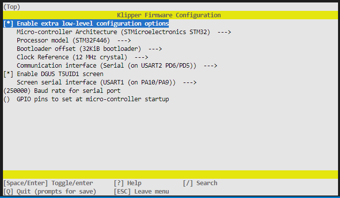 My Octopus Pro board was damaged while moving and the SD card cover was ripped off, so I programmed the board via USB; make sure to add a Boot0 jumper (located just above Drive0 and right after a row of headers for the WIFI module).
Raspberry Pi Mods
There are a few tweaks to the Raspberry Pi to allow you to communicate over the GPIO pins rather than USB. Huge shoutout to Chris Riley and his YouTube video on connecting an SKR Pico to a Raspberry Pi Zero for the m https://www.youtube.com/watch?v=ZOL-motmkos, this was a huge help in getting this working. I highly recommend giving his video a watch, but the main points required are as follows.
- Update the /boot/config.txt file to add the following 2 lines at the very end:
dtoverlay=pi3-miniuart-bt
dtoverlay=disablebt - Run the commands:
sudo systemctl disable hciuart.service
sudo systemctl disable bluetooth.service - Update the /boot/cmdline.txt to remove the following section:
console=serial0,115200
Configuration
Rather than taking the default Klipper configuration for the Octopus Pro and adjusting it to work for my Ender 5 Plus, I started with my SKR mini E3 v2 and adjusted it to work for the Octopus. The final configuration is on my GitHub page here: https://github.com/Cattux/Ender5Plus.
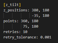
Really all that had to be done was to change every pin reference to the new pin name, but I also had to add a section for the Z1 stepper and a section for the Z tilt. The z_positions parameter is the actual location of the bed pivot points, or the center of the lead screws in my case. These positions aren’t actually reachable by the printer, so just estimate or get as close as possible and measure the difference with a set of calipers. The points parameter is where you actually want to probe. In my case X=360 is my end stop and puts the BL Touch about 45mm from the edge of the bed, so that’s my first point. I moved my nozzle to where the BL Touch was about 45mm from the other edge and used that as my second point. The Z tilt section looks like this:
Finally because I’m using UART to communicate between the 2 boards, my MCU section looked like this:
[mcu]
serial: /dev/ttyAMA0
restart_method: command
Installation
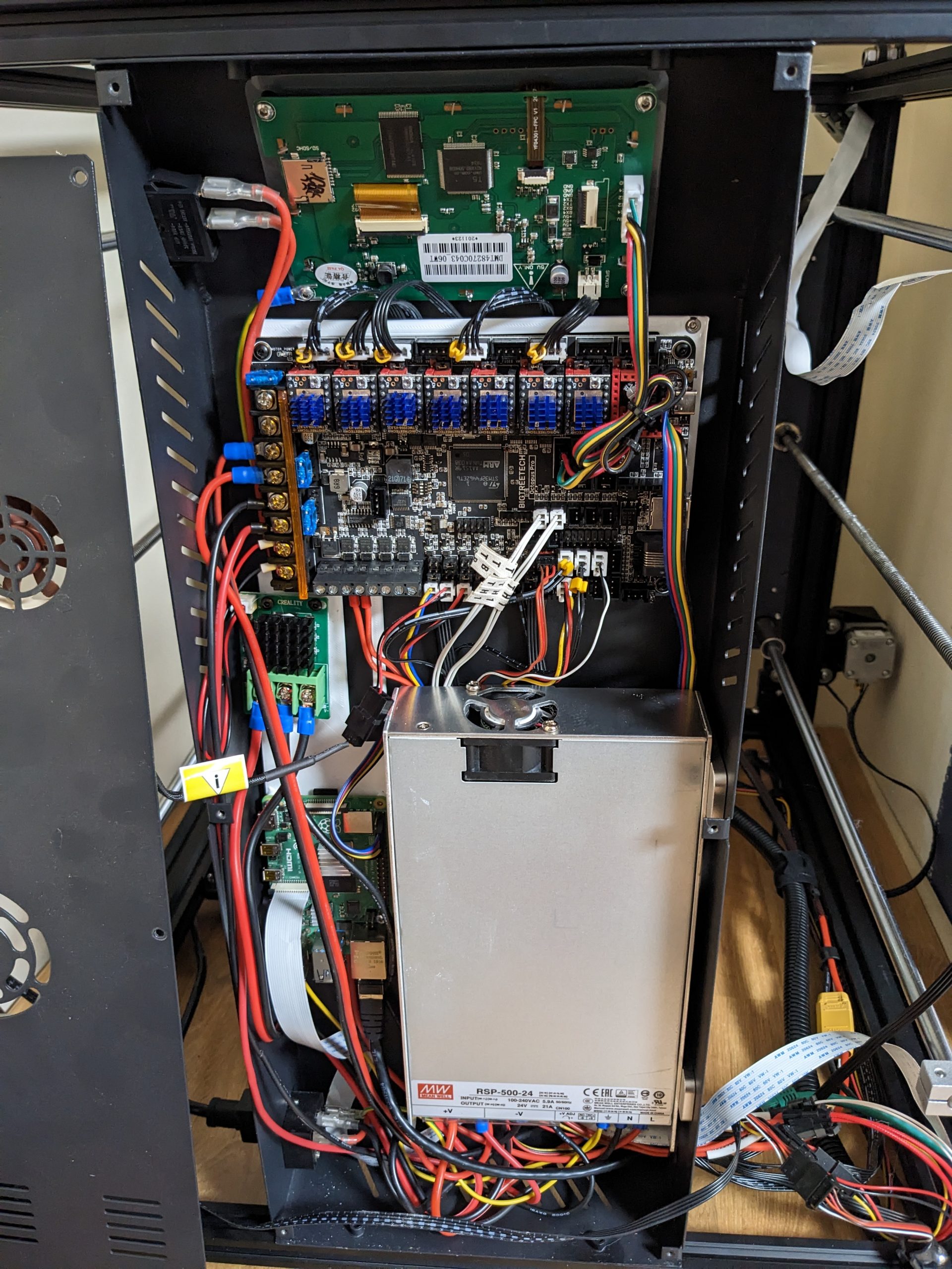
To install the raspberry Pi and Octopus Pro inside of the stock enclosure, I designed and printed a mounting plate. This was annoying as this printer was the only one I have that is big enough to print it and in order to confirm it was correct the printer needed to be taken apart. I had to print it twice to get it to work which meant putting the printer back together and taking it apart 1 extra time after the first version didn’t fit.
Note the stepper motor ports are X, Y, Z0, Z0′ (unused as I want independent Z motors), Z1, blank (future Z2), E0, blank (future E1), blank (future E2?).
I had previously rewired the BL Touch probe to fit the SKR Mini E3 v2 board, this was with a dupont connector (brown red orange) and a JST connector on the Z stop wires. The dupont connector wires were in the right order still, but the Z stop as well as the X and Y stop were all 2 pin jst connectors and the Octopus has 3 pin ports, so these 3 connectors had to be depinned and put into 2 pin connectors.
This shouldn’t have happened, but instead of using the bl touch dedicated connector, I had to use the neo pixel and an end stop connectors. The BLTouch ground to 5V was giving out -1.3V for some reason and I couldn’t figure out why. Maybe it’s related to the damage to the board from the SD Card slot cover getting ripped off, or maybe it’s a defect in the board, but it wasn’t a big deal expect for a few hours of debugging time. The pinouts for every connector is listed on the BTT GitHub repo for the Octopus, so it was easy enough to re-pin the jst connector of the BLTouch to have the pins in the right order for the neo pixel layout and plug the sensor wires into another end stop. Not ideal, but it’s all working in the end.
Test/Tune
So far I’ve confirmed that the printer can home and the hot ends heat up, now time to tune the PID for the bed and extruder heaters
PID_CALIBRATE HEATER=extruder TARGET=200
PID_CALIBRATE HEATER=heater_bed TARGET=60
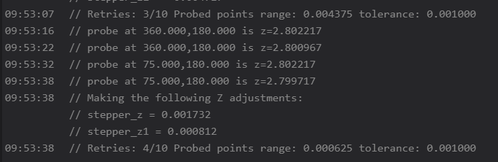
Before we move onto bed leveling, it’s time to adjust the Z tilt and make use of our independent Z steppers! This is done with the Z_TILT_ADJUST command which probes your two points and makes adjustments between each set to eventually get the points within your specified tolerance, mine took attempts:
Now we can calibrate the Z offset between the probe and the actual nozzle. Use the Probe Calibrate command to start the adjustment GUI and creep up on your piece of paper until it’s snug.
PROBE_CALIBRATE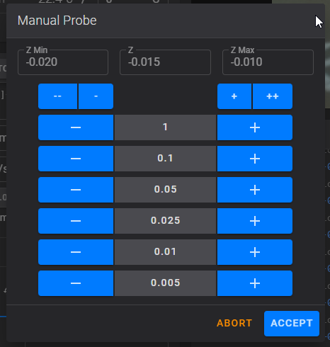
SAVE_CONFIG
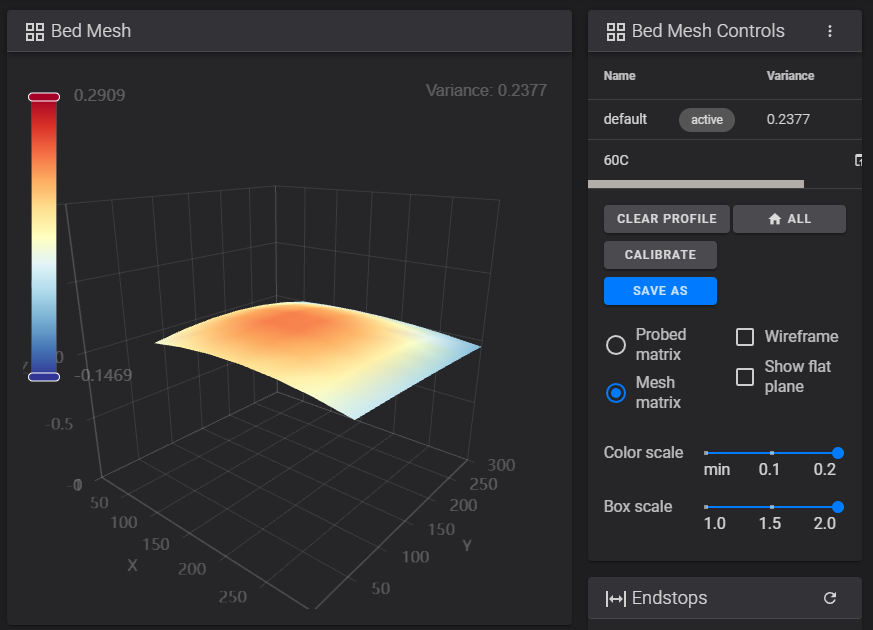
Now we can finally calibrate the bed mesh, but it’s best to do this when the bed is hot as it might have a different bow when hot or cold. I do most of my printing at 60C, so I’ll preheat the bed to 60 and then either run the following command or go to the Tuning tab in Fluidd and click “Calibrate”:
Let it do it’s thing, adjust the corners and run it again, repeat until you’re happy with how level the bed is and then save the configuration. I’m not super happy with the variance I ended up with, but it’s as flat as I can make it since the bed does has a significant bow. It’s not unreasonable for such a large bed, but more than I was hoping for.
Results
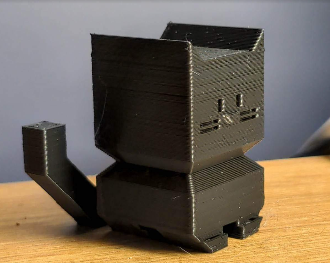
Finally, time to do a test print, I like to use the calibration cat to make sure the printer is working well. My filament has been sitting in the garage for 6 months after moving, so while I wait for a roll to come out of the dehumidifier, I ran a nested cali cat through the printer with a “wet” filament; I had to make a live tweak to the Z offset, but I got a successful print!
Next Steps
I’d like to tune the print with an accelerometer attached to the print head, so mounting that and connecting it to Klipper is one of my next projects.
I noticed while setting up the Z tilt that there are 15mm of the left side of the bed that the nozzle can’t reach, this is because the BL Touch mount would physically hit the frame. I’ve been considering making a Voron style print head for the Ender 5 with the BL Touch mounted in the center, this would remove that issue and give me an extra 15mm of printing space in the X axis. Totally not necessary as I rarely need to print anything wider than 360mm, but I would like to try out different hot ends and the Afterburner would be a good platform to build from; the added print space would be a minor extra benefit. 🙂
Finally, I’m not sure I’ll do anything but it might turn out to be annoying that I need to take the case off and plus a USB into the board to flash it, I might rethink the UART connection in the future. That being said, even if it was plugged in via USB, I would still need to manually install and remove the Boot0 jumper, so it’s maybe not that much of an inconvenience. I’ll consider making a jumper cable that is controllable via the Raspberry Pis GPIO, if I do that then I could reprogram the whole printer without opening the case, in which case the USB connection would be required.