I’m trying to give MySensors another chance; I gave it a half-hearted attempt when I first got started with home automation, but never got very far.
I’m going to demo this with an OG Raspberry Pi B and if it works and I like it, I might transfer it over to another Pi that’s already running elsewhere. I also might just leave it alone on the OG Pi, but we’ll cross that bridge when we get to it.
Before I get into this, the reason for giving this another shot is that up until now, I’ve mostly been able to get away this hard wiring in various sensors. I’m now at the point where I’m starting to deploy wireless sensors, and I’m not super keen on adding even more WiFi devices to my network. The nice thing about MySensors is that they use a central gateway to speak to Home Assistant, but all of the sensors communicate over RF. So in theory, if my WiFi is down but my network is still online, I can still get my sensor values. In reality, my WiFi is not likely to be down and not my network, the real benefit for me is that the sensors will not be adding unnecessary traffic to my WiFi network. They also create a mess network like Zwave, so the more devices you have, the better they can communicate back to the gateway. I’m hoping to be able to make some very low power sensors that could run off of batteries and maybe a solar panel, which I think would be a great use for this system.
Hardware
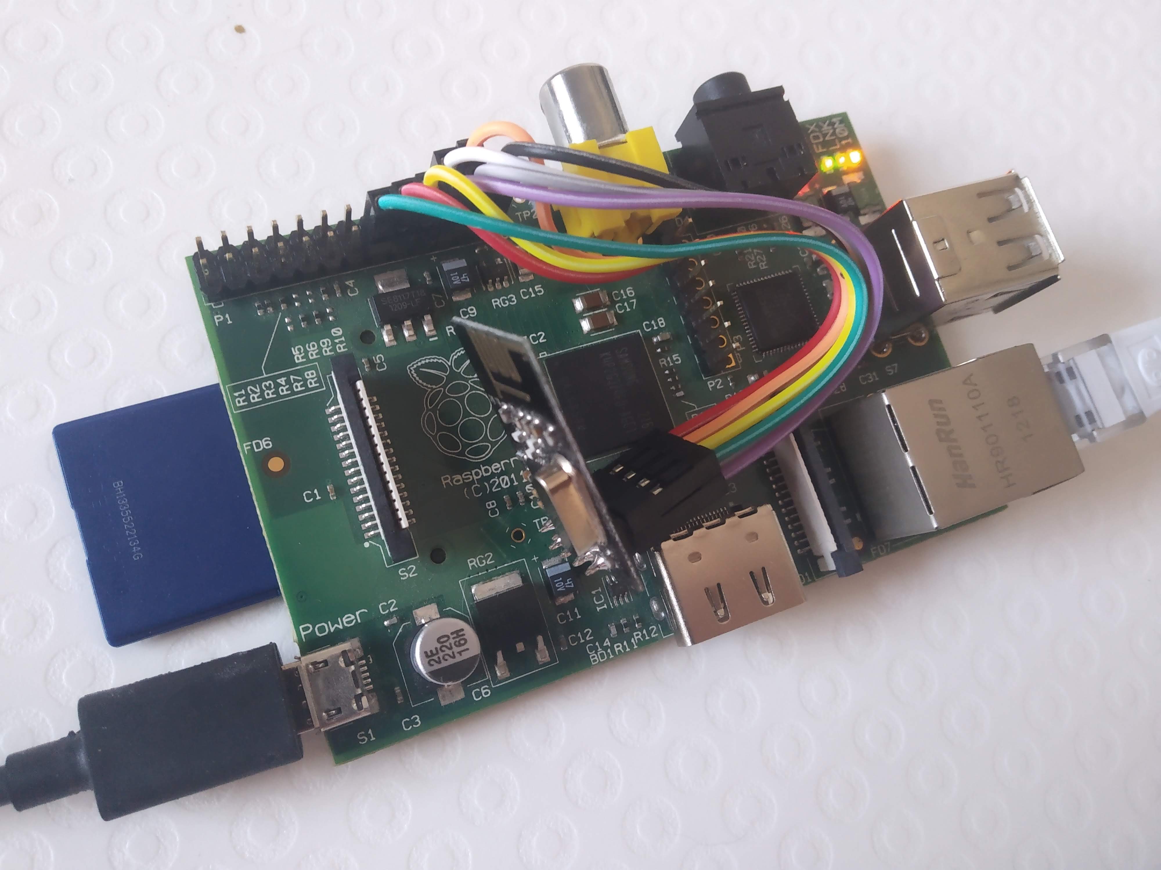
Pretty much just follow the instructions, just make sure to use the pin numbers and not the GPIO numbers. I used an original Pi B and a “NRF24L01+ 2.4GHz Antenna Wireless Transceiver Module” from Aliexpress. There’s an obvious short risk in my picture, I plan on securing the module better when I deploy it, or at least placing an insulator between the Pi and the module.
Building the Service
To start, I downloaded a fresh copy of Rasbian lite and flashed it to a 4Gb SD card with Etcher. Then the usual house keeping things like changing the default password, assigning a hostname (MySensors in this case), and enabling SSH so that this unit can be headless.
With that out of the way, I started following the instructions on their website for a Raspberry Pi. For the most part, I just followed their instructions, but I didn’t find them super clear so I’ll document some of the clarifications that helped make things click for me.
1. download the dev branch, not the master. I’m honestly not sure that the dev branch is required, but I switched to it while debugging and never switched back.
git clone https://github.com/mysensors/MySensors.git --branch development2. go into the MySensors folder
cd MySensors3. Configure the build of MySensors service. All flags must be set at the same time, if you forget one, you need to append it to your previous one, not just run that one that you missed.
This is all straight out of the instructions, but this is my final version. As you read through the instructions, you realize you should have added another flag and then need to go back and do it again.
./configure --my-gateway=mqtt --my-controller-ip-address=192.168.1.10 --my-mqtt-publish-topic-prefix=mysensors-out --my-mqtt-subscribe-topic-prefix=mysensors-in --my-mqtt-client-id=mygateway01 --my-transport=rf24 --my-rf24-irq-pin=15 --my-leds-err-pin=12 --my-leds-rx-pin=16 --my-leds-tx-pin=18- –my-gateway=mqtt
- I’m adding this gateway to my existing MQTT server
- –my-controller-ip-address=192.168.1.10
- This is the IP address of my MQTT server
- NOT the IP address of the Pi that we’re working on
- –my-mqtt-publish-topic-prefix=mysensors-out
- the MQTT topic for sensor values going to HA
- –my-mqtt-subscribe-topic-prefix=mysensors-in
- the MQTT topic for sensor values going to the sensors
- –my-mqtt-client-id=mygateway01
- the name of the gateway that will be presented to the MQTT server
- –my-transport=rf24
- the type of RF module I’m using
- –my-rf24-irq-pin=15
- A fix for a bug with the RF module that I’m using
- –my-leds-err-pin=12 –my-leds-rx-pin=16 –my-leds-tx-pin=18
- 3 optional LEDs that indicate the state of the gateway.
- Not 100% sure that I’ll use them, but it can’t hurt to add them for now.
4. Run make to compile the MySensors service
make5. Test that the service is working: Can talk to the RF module and the MQTT server.
sudo ./bin/mysgw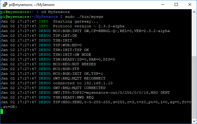
The test was successful… eventually.I ran into a bunch of problems before I got this far, the biggest contributor was a potentially faulty Gnd or 3.3V pin on the Pi, or a bad wire. After rewiring the RF Module to the Pi a bunch of different way, I eventually got it working, but it was never clear what the smoking gun was.
The other issue I had was that the example they give you assumes you’re running this on a Pi that is also your MQTT server, which is why the default value for the flag “–my-controller-ip-address” is localhost. This caused me a bunch of grief mostly because the name of the flag is also confusing, I didn’t realize it was supposed to be the MQTT IP address until I realized there was nowhere else to actual give the service the MQTT IP.
6. Install the service:
sudo make install7. Set the service to auto run when the Pi boots:
sudo systemctl enable mysgw.serviceBuilding a Sensor
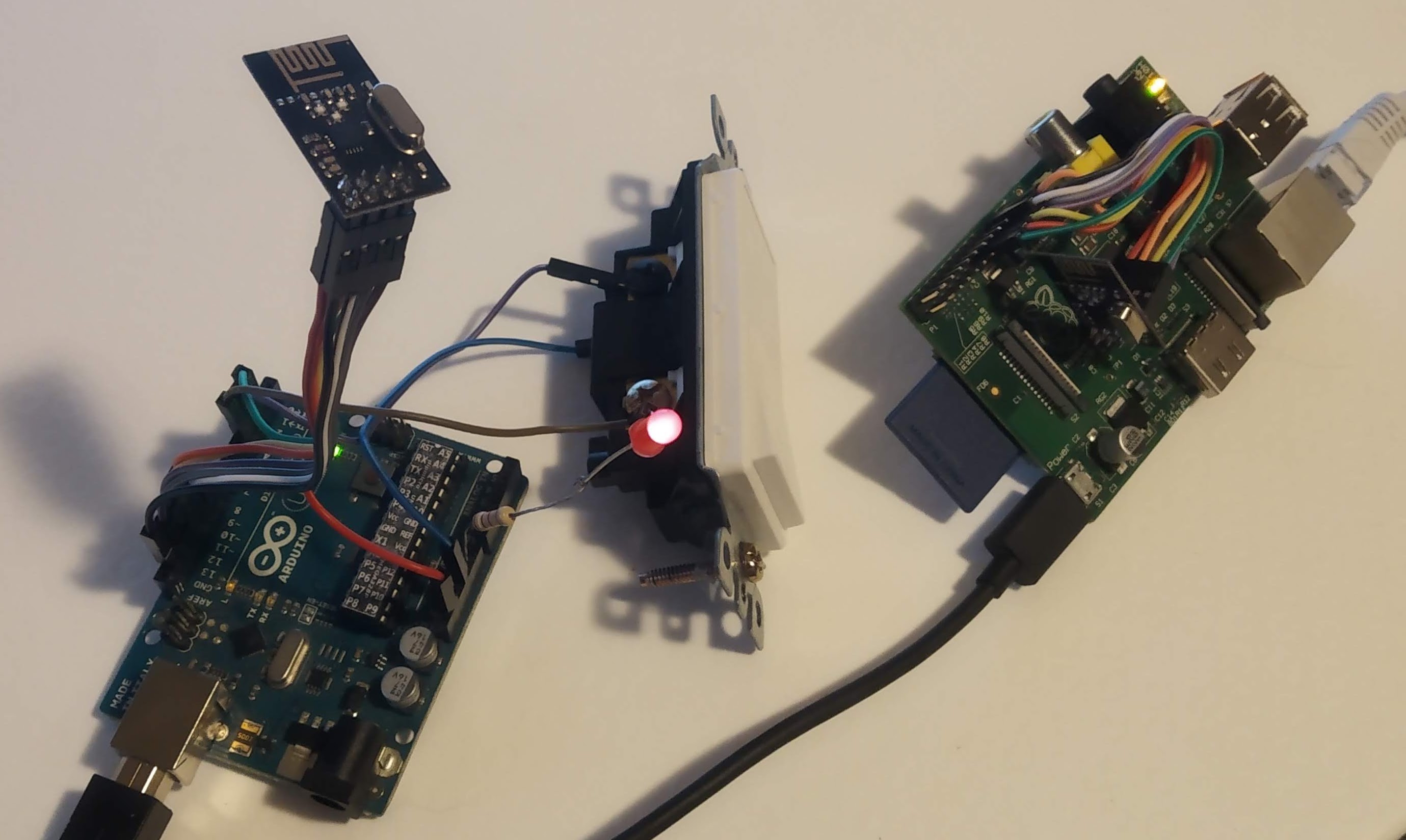
My first sensor is going to be an Arduino Nano that will eventually live in a wall acting as a low voltage smart switch. Basically all it needs is an input and an output. Lucky for me there is a perfect example on their website, so I can test this without too much code writing.
Looking at this example, there are 4 main steps. Wiring the RF module to the Arduino, wiring the input and output on the Arduino, setting up the Arduino environment on the PC, and flashing the code.
1. Wiring the RF Module is pretty simple, just follow these instructions for the “NRF24L01+ & Arduino”.
2. Wiring the input and output to the Arduino is even easier. In this case, I’m only going to wire the button in, for the output I’m going to test it with the built-in LED.
3. Setting up the Arduino environment… Follow these instructions.
4. Flashing the code for the sensor is basically just copying the code directly from the example, updating any pin changes as required, selecting the correct board and port, and uploading the code.
Well that was an understatement… Turns out the Arduino Nano that I was using is the 168 version, which doesn’t have all of the features as the 328 version, and it also has less memory.
For now I’ve switched over to an Arduino Uno, it’ll do well enough for testing purposes but I’ll need to tweak my plans for housing this in the wall.
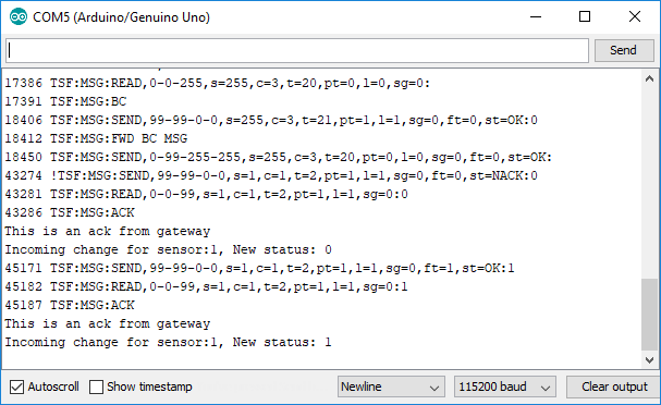
Testing
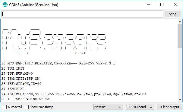
With the code from the Relay example above flashed onto the Arduino Uno, I was able to open the serial terminal to check the status. Once again, errors… It seems that the Arduino can’t communicate with the RF module. After testing a few modules, double and triple checking my wiring, I rewired the whole thing with entirely new jumpers. That did the trick, which is super annoying since you don’t usually expect wires to be bad. I threw those 8 wires out and resumed testing.
With the connection working, I tried out the “button” which is actually a standard wall switch. When the switch was flipped one way, nothing happened, but when it was flipped by the LED lite up. Flipping the switch up and down again turned the LED off… which is exactly how it should work since this example was written for a button, lol.
I think that’s where I’m going to leave this post for right now. I’ll do a follow up with integrating this with Home Assistant and hopefully the final code for the Arduino so that I can mount it in the wall. See ya soon!